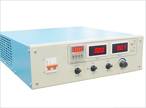
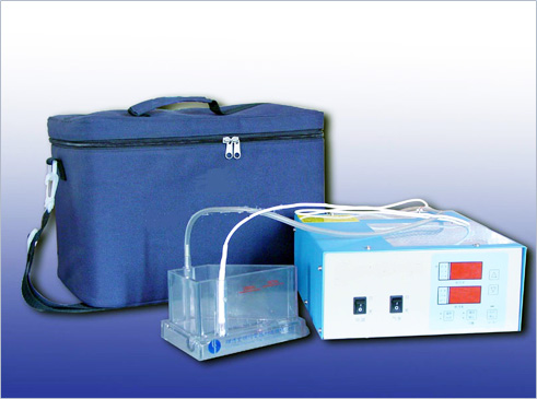
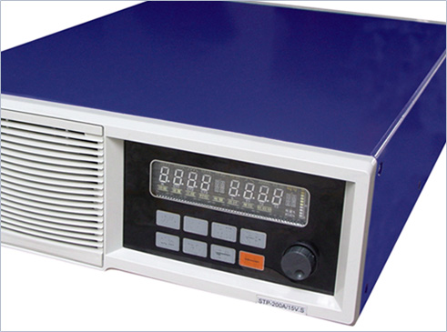
Our Switchmode rectifiers are suitable for Electroplating, Electropaint and Electrophoretic processes. Utilising modern electronic circuitry, they are more compact than traditional SCR rectifiers, offer a smoother output and come with a process timer as standard. Control is achieved either locally (on the rectifier), remotely (on a remote box), via a PLC controller (as part of an automated process), or a combination of control options. Our rectifiers also have Constant Current / Constant Voltage facility which enables the user to operate either constant amps processes or constant voltage processes. Digital metering of the Current and Voltage allow users to easily see the current and voltage being used at any time during the process. Along with various options that the user can specify when ordering make our rectifiers the first choice for many people in the Electroplating, Electropaint and Electrophoretic industry.
Available Options:
- Manual polarity reversing facility (toggle switch).
- Automatic polarity reversing facility (timers).
- Intelligent Ampere / Hour controlled.
- Variable pulse width output.
- Touchscreen control (usually used with high voltage output and PLC terminals).
- Output ‘over-voltage’ alarm box with relay output.
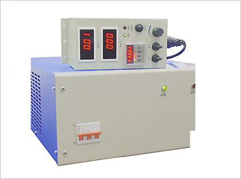
- Panel or freestanding remote.
- 5, 10, 15, 20 – 50 Mtr remote lead.
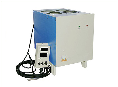
- Fresh air cabinet with fan.
In the past, a rectifier typically consisted of two, three, or four large components, namely a voltage regulator or variable transformer, a rectification unit, where necessary, a polarity reversing unit, and a control panel. Automatic control was either non-existent or very ‘hit and miss’, with operators often having to stand watch over the rectifier to ensure consistent quality of the process.
Obviously a lot of valuable floor space was used up in the siting of these units which were often connected to the process tanks using solid aluminium or copper busbars, with bolted or clamped joints. This meant that rectifiers were sited very close to the process tanks which caused problems due to condensation and contamination of the units.
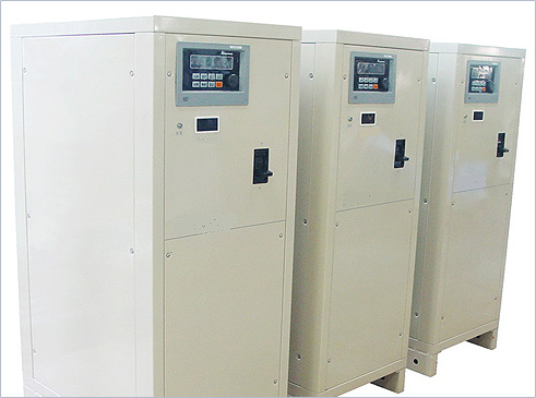
Today’s units are designed to be situated away from the process tanks or placed close to the process tanks in enclosures which have a fresh air feed. The control electronics are segregated from the DC power side to help keep them clean and all parts are further protected with a covering of protective varnish.